Product Overview
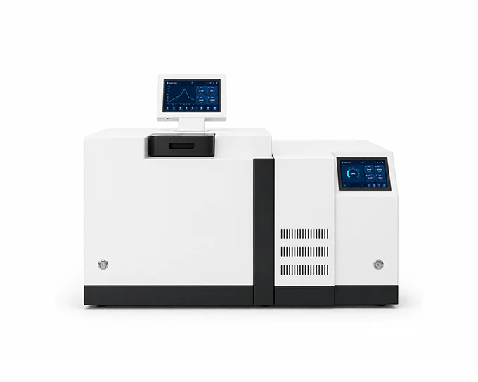
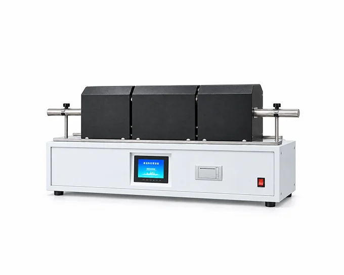
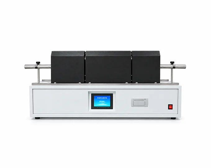
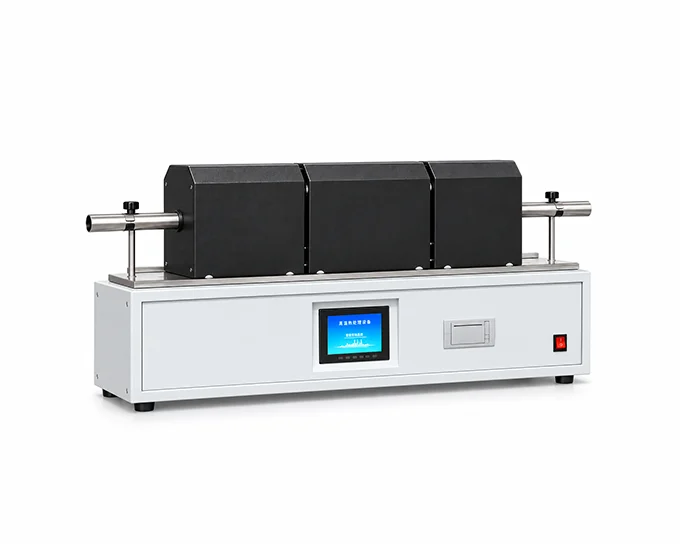
The Automatic Carbon and Hydrogen Analyzer determines the carbon and hydrogen content of coal and other organic materials. It is designed for laboratories in the coal, chemical, metallurgical, power-generation, and geological exploration sectors. The instrument combines controlled high-temperature combustion, process monitoring, result calculation, storage, and printing through a large color touchscreen interface. An optional nitrogen-analysis module can be integrated for laboratories requiring expanded elemental testing.
How It Works
The sample is completely combusted in a high-temperature oxygen atmosphere. Carbon in the sample is converted to carbon dioxide, while hydrogen is converted to water vapor. After interfering gases are removed, the water and carbon dioxide are captured by their respective absorbents. The increase in mass of the absorption tubes is entered into the system, which calculates the mass percentages of carbon and hydrogen in the sample.
Key Advantages
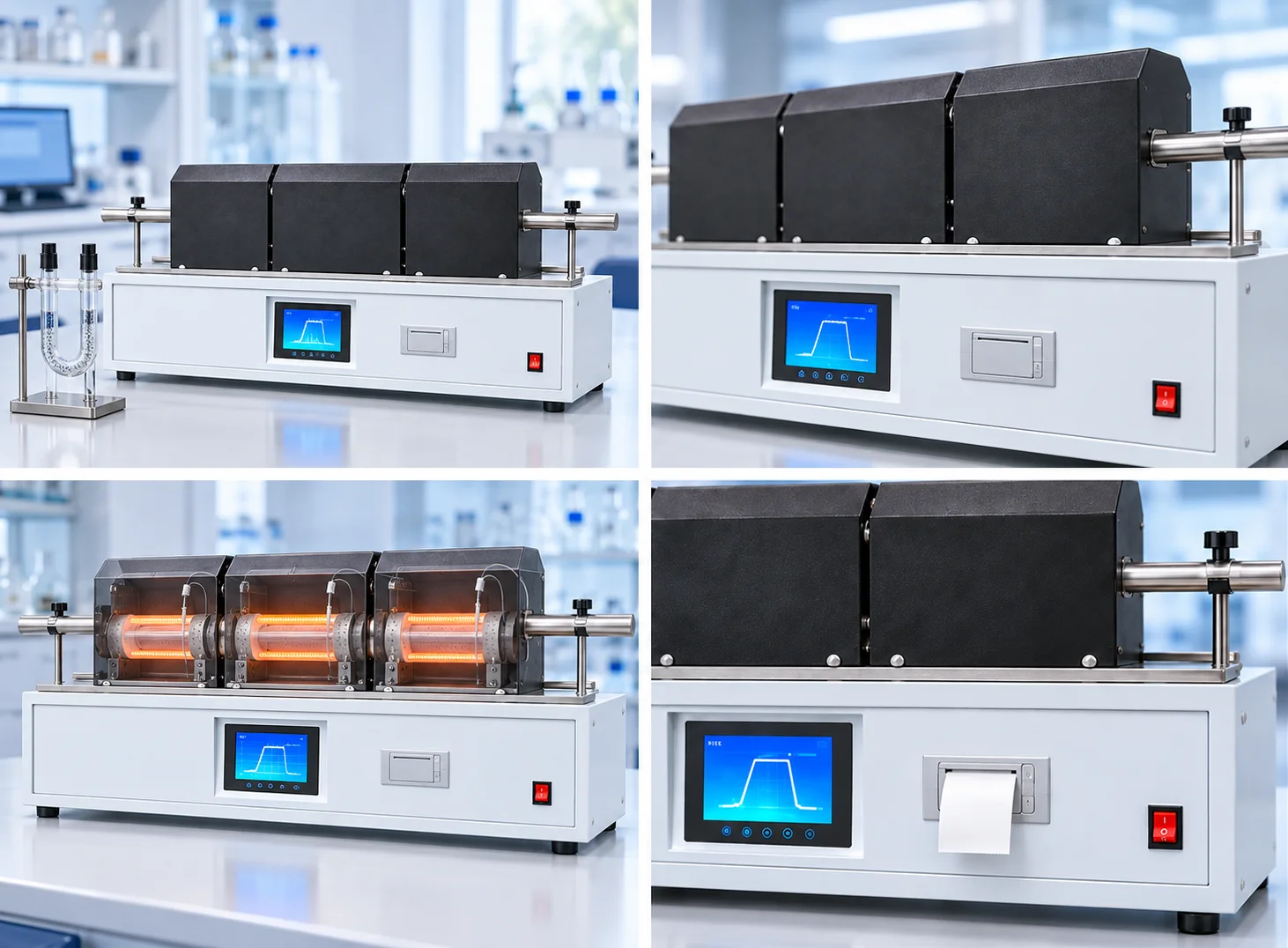
A large color LCD touchscreen presents test parameters, process status, prompts, and results in a clear and intuitive format.
PID algorithms and fuzzy-control technology automatically correct the measured temperature and regulate the thyristor firing angle to control furnace heating power.
Real-time process prompts guide the operator through the test. After the absorption-tube weight gain is entered, the system calculates, stores, and prints the completed test result.
Independently specified furnace sections provide controlled combustion, oxidation, and downstream treatment conditions along the combustion tube.
The system is designed for carbon and hydrogen determination and can be paired with an optional nitrogen-detection module when required.
Applications
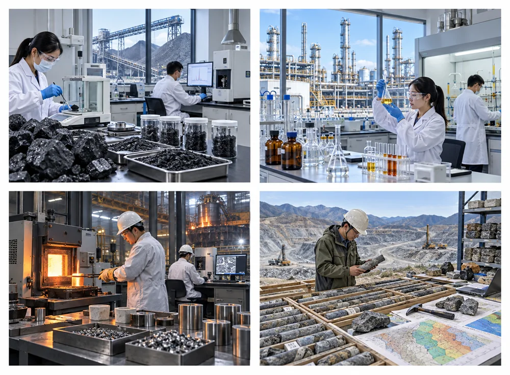
Suitable for coal-quality laboratories, chemical and metallurgical plants, power stations, geological exploration organizations, universities, research institutes, and industrial quality-control laboratories analyzing coal or other combustible organic samples.
Model Selection Guide
| Parameter | Specification |
| First Furnace Zone Temperature | 850± 10 deg C |
| Second Furnace Zone Temperature | 800± 10 deg C |
| Third Furnace Zone Temperature | 600± 10 deg C |
| Combustion Tube Dimensions | Outer diameter 20 to 22 mm; wall thickness 2 mm; length 1100 to 1200 mm |
| Combustion Tube Material | 1Cr18Ni9Ti stainless steel |
| Heating Element | Nickel-chromium wire, diameter 0.6 to 1.0 mm |
| Temperature Sensor | Class 2 Type K thermocouple |
| Rated Voltage and Frequency | AC 220 ± 22 V; 50 ± 1 Hz |
| First Furnace Zone Power | 1200 W |
| Second Furnace Zone Power | 1500 W |
| Third Furnace Zone Power | 800 W |
| Temperature Measurement Accuracy | ± 1 deg C |
| Temperature Control Accuracy | ±- 10 deg C |